
Corrugated Box Die Making Creasing Cutting Machine Solutions Improve Packaging Accuracy
2026-11-16
Packaging accuracy can make or break a supply chain. One slight misalignment in a corrugated box, and the whole line slows down—wasted board, rejected runs, frustrated clients. That’s where ADEWO die making, creasing, and cutting machines step in. Built for converters who refuse to choose between speed and precision, these solutions turn complex corrugated designs into repeatable, crisp results. Whether you’re running short custom jobs or high-volume production, the right tooling changes everything. Here’s how ADEWO helps you hit tighter tolerances and deliver boxes that fit—every single time.
Calibrating Crease Depth for Snug-Fit Carton Assembly
Crease depth sits at the heart of a snug-fit carton assembly. If the crease is too shallow, the board resists folding and tries to spring back, leaving flaps that bow outward and corners that never quite seat. Too deep, and you cut through the outer liner or crush the fluting, which weakens the fold line and invites cracking along the edges. The goal is to find that narrow band where the fold becomes a natural hinge—flexible enough to stay put, but strong enough to survive repeated handling.
Start by setting the creasing rule or wheel to a conservative depth and run a few blanks. Fold each sample along the crease and check for springback: the panel should hold a crisp 90-degree bend without drifting open. Increase depth in small increments, and after each adjustment, flex the fold both ways. A well-calibrated crease shows a faint whitening of the inner liner but no visible cracks or fiber separation. Keep a record of the final setting, and repeat the test on board from different stacks or humidity conditions, since thickness and moisture can shift the ideal depth by a noticeable margin.
Once the crease depth feels right in a hand test, move to a full assembly trial. Erect the carton and watch how the side walls meet the top and bottom flaps. If the flaps snap open or the corners bulge outward, the crease is still too shallow. If the fold feels floppy or you see a dark line of compressed board on the outside, the crease has gone too deep. Recalibrate whenever the board stock changes, the die-cutting tooling is resharpened, or the production floor humidity swings by more than ten percent—small shifts in crease depth are often what separate a snug, positive closure from a carton that fights the packer.
Die Blade Profiles That Reduce Panel Tearing
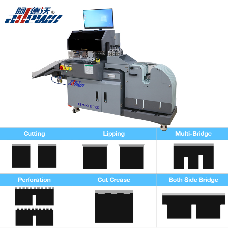
The geometry of a die blade's cutting edge directly influences how force is transferred into the panel surface. A straight, square-ground profile tends to concentrate stress at the initial contact point, which can rip fibers before the cut is complete. By shifting to a micro-beveled or dual-angle profile, the blade enters the material at a shallower angle, compressing the top layer instead of tearing it. This small change in edge geometry spreads the load over a slightly longer contact zone, giving the panel fibers time to separate cleanly.
Among the more effective profiles for reducing panel tearing are hollow-ground and asymmetrical grinds. A hollow-ground edge removes a concave section behind the cutting tip, reducing friction and heat buildup as the blade moves through dense panel stock. Asymmetrical grinds, where one side of the blade has a steeper angle than the other, create a shearing action similar to scissors. This is especially useful on laminated or veneered panels, because the bottom surface is supported by the shallower-angled side while the steeper side drives the cut, preventing chip-out on the exit side. Variable pitch profiles can also help by breaking up harmonic vibrations that otherwise cause micro-cracks along the cut line.
In practice, switching to a shear-face or multi-facet profile on a router bit or die cutter can cut edge tear-out by a significant margin—often in the range of 30 to 40 percent on high-density fiberboard and particleboard. Keeping the profile sharp and consistent is equally important; a tiny flat spot on the edge will reintroduce tearing almost immediately. Matching the profile to the panel's thickness and resin content usually matters more than increasing feed rate or spindle speed, because the edge geometry determines how cleanly the fibers are severed rather than how fast the tool moves.
Synchronizing Feed Speed and Cutting Pressure for Consistent Output
On many cutting tables, operators tend to chase a single dial at a time. They bump the feed rate up to beat a deadline, then wonder why the cut edge suddenly shows heavy dross or a ragged bevel. The missing piece is almost always cutting pressure. Feed speed and pressure act like dance partners: if one moves without the other, the result is a stumble. A fast travel speed with low pressure leaves unmelted islands and a weak arc, while high pressure at a slow crawl overheats the material and widens the kerf. Neither scenario produces parts you can send straight to the next station.
A better routine is to treat the two parameters as a single adjustment. Before you touch the speed knob, note your current pressure setting and the thickness of the stock. Then change both by a proportional amount, starting with a small step, and run a test piece the length of your hand. Look at the backside of the cut, not just the top face. If the underside shows a fine, even line of solidified metal, you are close. If it is spattered or missing, adjust both dials again in the same direction you moved the first time. After a few test strips, you will build a mental map for that material and thickness, and the cuts will hold their quality across the entire sheet instead of drifting after the first few parts.
Why Micro-Adjustable Guides Improve Blank Alignment
When you're setting up guides on a rod blank, even a fraction of a degree off center can pull the line path sideways under load. Micro-adjustable guides let you nudge each guide a hair at a time while sighting down the blank, so the ring centers stack perfectly along the intended axis. This matters most on light-power blanks where a slight twist in guide alignment shows up as uneven curve during test casting.
Instead of loosening, shimming, and re-tightening standard supports, you turn a fine-thread adjuster to shift the guide left or right without losing your vertical reference. That means fewer rechecks, less frustration, and a cleaner final wrap. Once the guide train follows the blank's natural bend, load distributes more evenly and the rod tracks straighter when fighting a fish.
Placing Creases to Prevent Box Skew and Edge Crush
Crease placement determines whether a box folds square or fights you at every joint. When front and back scores don't line up within half a millimeter, the blank shifts during folding and the finished carton takes on a slight parallelogram shape. That skew becomes worse under load because the vertical panels no longer share weight evenly. A quick check is to fold a sample flat and measure the gap between opposite corners before the glue sets.
Edge crush starts where a crease is pressed too deep or placed too close to a cut edge. A rule that bites through the liner breaks the fiber instead of guiding it, so the corner loses its column strength. Moving the crease back by the thickness of the board and using a narrower, rounded profile scoring rule keeps the outer liner intact. On corrugated stock, a two-point crease with the female channel width set to 1.5 times board caliper gives a fold that flexes without cracking at the shoulders.
From Sample to Full Production: Holding Cut Tolerance Without Manual Checks
Transitioning from initial samples to full-scale production often exposes a weak point in cutting operations: maintaining tight tolerances without relying on operator intervention. In prototyping, a skilled machinist can nudge offsets or swap tools frequently, but at production volumes that approach breaks down. The real requirement is a process that holds dimensional accuracy as an inherent property, not a corrective action.
One practical way to achieve this is through in-process measurement tied directly to machine control. For example, touch probes or laser scanners can check critical features after each cut, and the control system adjusts offsets automatically based on measured deviation. Combined with tool wear modeling, this keeps the cutting edge performing within a defined window. Statistical tracking of these adjustments also flags drift before it becomes a rejected part, so manual inspection becomes a periodic audit rather than a per-piece gate.
In practice, plants that make this shift see fewer surprises between first article and thousandth article. The tolerance band stays predictable because the feedback loop runs continuously, not when someone remembers to check. It also frees operators to manage multiple cells instead of standing over a single machine with calipers. That is the difference between sampling confidence and production certainty.
FAQ
Small deviations in cut or crease placement change how flaps meet, how corners align, and how much stacking strength a box retains. When cuts are off by even a millimeter, gaps appear at the joints, tape adhesion weakens, and the box may fail under load. Accuracy keeps the structural geometry intact, so the finished box protects the product instead of just containing it.
Older systems often struggle with inconsistent crease depth across the sheet, ragged edges on complex cutouts, and uneven pressure on multi-flute board. This leads to cracked scores, poor folding resistance, and higher rejection rates. Upgraded die making and creasing cutting machines solve this by maintaining uniform pressure, using servo-driven registration, and adjusting for board thickness in real time.
Instead of relying on fixed tooling settings, modern systems read the board thickness and flute type before the sheet enters the cutting zone. They then adjust creasing depth, cutting pressure, and dwell time automatically. For B, C, E, and even double-wall board, this means operators no longer stop the line to swap out pads or re-zero the die.
Yes, and that is the main shift in current packaging lines. By integrating cutting and creasing stations into a single servo-synchronized sequence, the sheet is processed in one handling step. This reduces registration drift between processes, eliminates a transfer point, and actually increases net throughput because you remove the time lost aligning sheets twice.
The biggest accuracy killers are worn anvil covers, dulled cutting rules, and drift in the creasing matrix. A practical routine includes checking anvil condition weekly, sharpening or replacing rules based on sheet count not just visual wear, and verifying crease depth on a sample at every shift change. Keeping the stripping area clean also prevents small scraps from throwing off sheet positioning.
Automated systems use optical registration marks to position each sheet precisely before cutting, so misaligned blanks are caught before they become finished boxes. They also optimize cutting patterns to nest more boxes per sheet and reduce trim waste. The result is fewer rejected sheets, less corrugated board going to scrap, and a measurable drop in cost per thousand boxes.
Look for independent servo control on both the cutting and creasing stations, not just a single drive running everything. Ask about the minimum crease width the machine can hold on E-flute and double-wall. Check whether the registration system reads the board edge, printed marks, or both. And request a trial run with your most demanding box style to see how the machine handles tight tolerances at production speed.
Cutting force determines whether the blank separates cleanly, but creasing pressure controls how the box folds. Too much pressure cracks the liner, too little creates a weak fold line that drifts. Accurate pressure control creates a uniform crease profile across the sheet, which means consistent folding on every panel, better glue joints, and a box that sets up square without operator adjustment.
Conclusion
Getting the crease depth exactly right on a corrugated box die cutting machine isn't a one-time setting—it shifts with board caliper, moisture level, and flute profile. Operators who calibrate depth against the actual sheet instead of relying on the die maker's default see immediately tighter carton assembly, with flaps closing without bulging or gapping. Paired with blade profiles that cut cleanly through the liner rather than crushing the corrugated medium, tear-out along panel edges drops sharply. The real difference comes when feed speed and cutting pressure are tied together: if the ram cycles faster than the sheet can settle, you get shallow creases at the lead edge and deep cuts at the tail. A closed-loop adjustment that trims pressure as speed ramps up keeps every blank within a narrow band, so downstream folding and gluing don't have to compensate for erratic scores.
Micro-adjustable side and front guides address the smaller misalignments that accumulate into skew, especially on multi-up layouts or recycled board with varying stiffness. A shift of half a millimeter at the guide translates into a box that twists when erected, and that twist puts uneven load on the crease, eventually crushing the edge. Placing creases with a slight offset around high-stress corners—rather than exactly on the theoretical fold line—also prevents the outer liner from cracking under compression. Once these settings are locked in, the step from sample approval to full production no longer depends on periodic manual checks. Inline sensors tracking crease depth and cut length at running speed flag drift before it produces a bad stack, so tolerances hold from the first sheet to the last pallet without someone standing at the delivery end with a caliper.
Contact Us
Contact Person: KAELYN LEE
Email: [email protected]
Tel/WhatsApp: +86 15012673758
Website: https://www.china-adewo.com