
ODM Flange Penstock Gate Design and Installation Best Practices for Hydropower Systems
2026-08-20
At the heart of every hydropower system, the penstock gate is a silent gatekeeper—until it isn't. A flange that's slightly off-spec, a seal installed in the wrong sequence, or a torque pattern guessed instead of calculated can turn routine maintenance into an emergency shutdown. ODM flange penstock gates offer a way to avoid those surprises, but only if their design and installation follow proven best practices. This guide walks through what actually matters: flange face alignment, gasket selection, bolting procedures, and commissioning checks that catch problems before water does. Because the goal isn't just a gate that fits—it's a gate that holds. That's why teams spec THT when they can't afford to learn lessons the hard way.
Flange Bolt Tensioning Without Distorting the Gate Seal
Even torque on flange bolts keeps the gate seal geometry stable. Start by marking each nut and stud with a reference line, then pull tension in a star pattern. A two-pass approach—first to roughly 60% of the target load, second to full value—lets the gasket settle without pinching one side of the gate.
Watch the seal gap as you go. If the gate starts to bind or the gap closes unevenly, back off the nearest bolt pair and re-tension in smaller increments. For high-pressure seats, switching to hydraulic tensioners instead of torque wrenches reduces flange rotation and local stress at the seal face.
Finish by checking runout with a dial indicator around the flange. Any deviation beyond a few thousandths suggests the gate is being pulled out of plane. Releasing the bolt load in reverse sequence and starting over costs less than a scored gate or a leak on startup.
Matching Gate Materials to Penstock Pressure Fluctuations
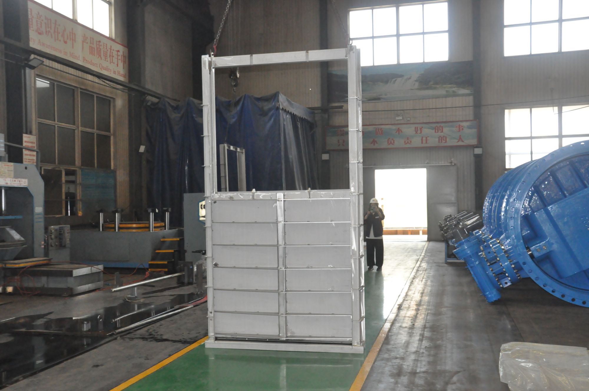
Gate material selection for penstock service often gets reduced to a single static pressure rating, but the real demand comes from how pressure swings propagate through the system. Rapid guide vane adjustments or emergency closure can generate water hammer spikes that push stress reversals deep into the gate leaf and its seals. Under these fluctuating loads, a material that performs well in a steady tensile test may still develop fatigue cracks at stress concentrations near the trunnion or seating faces. Duplex stainless steels tend to handle this better than standard carbon steels, not just because of higher yield strength, but because the ferrite-austenite microstructure interrupts crack propagation and offers more uniform strain hardening under cyclic conditions.
Beyond metallurgy, matching a gate to pressure fluctuations also means looking at damping and stiffness rather than chasing maximum hardness. A very rigid gate can transmit pressure pulsations directly into the embedded guides, causing fretting and loosening over time. Some designs now use nodular cast iron for the gate body in moderate head applications, since its graphite nodules provide natural vibration damping while still meeting structural requirements. For high-head or highly variable load profiles, a stainless steel overlay on the seating faces combined with a slightly more flexible composite stiffener arrangement can shift the natural frequency away from the dominant penstock pulsation band. The practical approach is to measure the actual pressure spectrum at the gate location, then select a material combination that avoids resonant amplification and resists the specific corrosion fatigue environment.
Aligning ODM Flange Faces Before Concrete Encasement
Achieving proper alignment of ODM flange faces before concrete encasement is a critical step that directly influences long-term joint integrity and load distribution. Even minor deviations in face parallelism or flatness can create stress risers once the concrete cures, leading to uneven bearing pressure or premature gasket failure during operation. Field crews typically begin by inspecting both flange faces for surface irregularities, burrs, or weld spatter that could throw off alignment readings. A common practice involves using a precision straightedge and feeler gauges across opposing bolt holes to verify that the gap remains consistent around the entire circumference. Any misalignment detected at this stage should be corrected before proceeding, as accessing the flange after encasement is both costly and time-consuming.
To bring the flange faces into alignment, mechanics often employ a combination of temporary shims, jacking bolts, and laser alignment tools. The goal is not merely to make the faces touch, but to ensure the mating surfaces are coplanar within the tolerance specified by the project's ODM flange standard, typically no more than 0.05 inches of deviation per foot of diameter. Adjustments are made incrementally, working from the bottom side upward to account for gravitational sag of the connected piping or equipment. Once alignment is achieved, the flange is temporarily bolted with a reduced number of fasteners at evenly spaced intervals to hold the position during formwork construction and concrete placement. It is essential to recheck the alignment after the formwork is in place, since the weight of the forms themselves can shift the flange if supports are not independent.
Maintaining alignment throughout the concrete pour requires foresight in the form of pre-installed anchor bolts, guide rods, or purpose-built alignment fixtures that remain embedded in the concrete. These elements serve double duty: they keep the flange face true while the wet concrete exerts lateral pressure, and they provide a reference plane for post-pour verification. A recommended sequence is to pour concrete in lifts, stopping after each lift to take quick laser or dial indicator readings on the flange face. If movement beyond tolerance is detected, immediate corrective action can be taken before the concrete sets. Only after the final lift has cured and all alignment readings fall within the allowable envelope should the temporary holding bolts be replaced with the full permanent bolt set at the specified torque. This disciplined approach prevents the costly scenario of discovering a skewed flange face after the structure is in service.
Installing Penstock Gates in Confined Hydro Plant Spaces
Working inside a confined hydro plant bay changes the entire approach to penstock gate installation. There is rarely enough headroom for a mobile crane to swing a full gate leaf into place, and the access openings often force you to bring the gate in as separate sections. Instead of relying on standard lifting charts, crews end up using low-clearance chain blocks, custom skid rails, and a lot of manual positioning. The gate sections get lowered through narrow hatches or moved along temporary beams, then jacked sideways to line up with the embedded guides. Every inch of travel has to be planned against the nearest wall, pipe rack, or concrete column.
Alignment in such tight quarters depends on reference marks that survive the entire installation window. Surveyors typically transfer centerlines and seal-seat elevations to the surrounding concrete before any steel arrives, and those marks become the only reliable guide once the space fills with equipment. Welders working on the gate leaf often have to crouch between stiffeners or lie on planking above the opening, so preheating, interpass temperature checks, and ventilation need to be arranged around that limited access. Bolted connections are sometimes preferred over full-penetration welds purely because there is no room to grind and inspect the back side.
Planning has to account for the fact that you may not be able to remove a damaged or misaligned section without cutting it apart. That means mock-up fits in an open area before the gate enters the confined bay, plus temporary lifting lugs positioned so a chain block can be re-rigged without moving a scaffold tower. Experienced crews also pair each movement with a spotter on the outside of the access door, because radio signal can drop and hand signals become the only form of communication. The result is slower than an open-air installation, but the sequence is repeatable and safer when every lift has a dedicated escape path.
Verifying Seal Compression Under Full Hydrostatic Load
Before placing any confidence in a seal's ability, it's worth asking how the compression set actually behaves once the cavity fills and pressure pushes evenly in every direction. Full hydrostatic load doesn't just squeeze a gasket from one side; it wraps around the exposed surfaces, seeking the path of least resistance. Watching the seal under that condition often reveals a different story than a simple bench-top compression test.
One practical approach is to instrument the flange or housing with small linear displacement sensors at three or four points around the seal. As the internal pressure ramps up, you record the change in joint separation. A seal that loses compression under hydrostatic pressure will show uneven gaps or a gradual relaxation that doesn't recover after the pressure bleeds off. In critical joints, comparing those readings against the original preload can identify whether the seal is still working or simply holding shape while the contact stress has already dropped below the sealing threshold.
It's also useful to run the verification with the actual mating surfaces, not polished test plates. Surface finish, flatness deviation, and bolt stretch under pressure all influence how well the seal stays compressed. If the measured compression loss remains within the material's recovery tolerance across a full pressure cycle, the seal can be considered stable for that load case.
Routine Checks That Extend Gate Service Life
Start with a slow walk around the gate while it opens and closes. Watch the hinges, rollers, and track for any wobble or hesitation. A gate that jerks slightly on one side is often telling you a bracket has loosened or a wheel is starting to flatten. Catching these clues early—before the metal wears into an oval—can save you from replacing the entire roller assembly later.
Keep the track and chain free of built-up grit, leaves, and old hardened grease. Instead of layering new lubricant over dirt, wipe the chain or screw drive with a rag, then apply a light coat of the lubricant recommended for your gate type. Over-lubricating attracts more debris and accelerates wear. A simple monthly wipe-down takes five minutes but keeps tension parts moving without extra friction.
Every few months, test the safety reverse and manual release. Block the gate’s path with a rolled-up towel and see if it stops and reverses quickly. Pull the release handle to move the gate by hand—it should glide without binding or feeling heavy in one spot. Any change in resistance or a new grinding sound usually points to a misaligned track or a failing bearing, which is much cheaper to fix while it’s still small.
FAQ
Start with the maximum surge pressure at the gate location, not just the static head, because water hammer can exceed normal operating pressure by a wide margin. Also consider the penstock diameter, flow velocity, sediment load, and whether the gate will be opened or closed under full differential pressure. Material compatibility with the water chemistry, especially in high-turbidity or corrosive environments, often rules out certain carbon steel grades unless they receive a robust coating system.
Misalignment between the gate flange and the mating penstock flange forces the bolts to carry bending loads instead of pure tension. That can lead to uneven gasket compression, localized leaks, and fatigue cracking at the bolt holes over time. Using alignment pins or temporary jigs before torquing the bolts helps keep the joint within the manufacturer's flatness and parallelism tolerances.
Metal-to-metal contact with an embedded elastomer or graphite-filled spiral wound gasket tends to perform well under high head because it resists blowout and maintains resilience during pressure cycles. For heads above roughly 300 meters, a double-seal design with a test port between the seals allows operators to verify primary seal integrity without depressurizing the entire penstock. Avoid soft rubber gaskets that can extrude through the flange gap when the head rises sharply.
Begin by dry-fitting the gate and checking that the flange faces are clean, flat, and free of nicks. Install the gasket dry unless the manufacturer specifies a compatible lubricant, then bring the bolts up in a star pattern to 30% of the target torque, followed by 60% and finally 100%. After 24 hours under operating pressure, re-torque the bolts to compensate for gasket relaxation and thermal movement.
Thermal expansion and contraction of the penstock shell can change the clamping force at the flange joint if the bolts and flanges are made from materials with different coefficients. In alpine hydropower systems, winter cooling can reduce bolt tension enough to cause weeping at the gasket. Using preloaded bolts with Belleville washers or selecting bolt material that matches the flange's thermal expansion rate reduces this seasonal loosening effect.
Inspect the flange joint for signs of rust staining, mineral deposits, or moisture after each major load cycle. Listen for bypass leakage around the gate seats when the gate is fully closed, which indicates wear or debris on the sealing faces. Every two to three years, remove and lubricate the spindle threads, and verify that the gate's guide rollers or slide tracks are not binding due to silt accumulation.
A gate selected only for static head may fail during transient events like emergency shutdowns or turbine load rejections, when pressure spikes can reach 1.5 to 2 times the normal operating value. Flange drilling, wall thickness, and seal design are all tied to the pressure class, so underrating the gate exposes the entire joint to deformation and fatigue cracking. Surge analysis should drive the design pressure, with static head used only as a minimum reference point.
Conclusion
When assembling ODM flange penstock gates for hydropower service, the first thing many installers overlook is how bolt tensioning pattern affects the gate seal. A star-pattern torque sequence with graduated steps keeps the flange face flat and avoids pulling the seal ring into an oval, which later causes uneven wear and leakage. Material choice matters just as much: gate bodies and shafting need enough ductility to absorb rapid pressure swings from turbine start-stop cycles without cracking at stress risers. Before any concrete pour, flange faces must be checked with a straightedge and feeler gauges across multiple diameters—small misalignments here turn into large binding forces once the penstock is buried.
In tight powerhouse layouts, rigging a gate into a narrow penstock gallery often demands rotating the assembly or using a temporary slide rail instead of a simple crane drop. After installation, filling the penstock slowly while monitoring seal compression under full hydrostatic head reveals whether the sealing faces are mating correctly; a drop in measured compression usually points to a twisted gate leaf or debris on the seat. Beyond commissioning, routine checks on flange bolt torque, seal lip wear, and stem packing condition do more for service life than any major overhaul. These practices—when applied together—reduce unplanned shutdowns and keep the gate operating smoothly through pressure transients and seasonal temperature swings.
Contact Us
Contact Person: Su Zhang
Email: [email protected]
Tel/WhatsApp: +86-25219206
Website: https://www.tht-valve.com/