
Ultrasonic Spray Nozzle Factory Processes That Boost Coating Quality
2026-08-14
Ever wonder why some coatings look flawless while others peel or streak within weeks? The secret often lies upstream—in the ultrasonic spray nozzle factory. At Siansonic, precision isn't just a buzzword; it's engineered into every nozzle through processes that most manufacturers overlook. From micron-level orifice drilling to acoustic tuning of the atomizing tip, each step directly influences droplet uniformity, pattern stability, and ultimately coating quality. Whether you're applying photoresist on wafers or antimicrobial layers on medical devices, what happens on the factory floor before the nozzle ships determines how well your coating performs. In this post, we'll walk through the specific factory processes that set Siansonic apart—and why they matter for your next coating challenge.
Where Droplet Size Is Decided Before the Nozzle Leaves the Bench
The droplet size is not a field adjustment; it is baked into the nozzle before it ever leaves the test bench. Every micron of the orifice diameter, the sharpness of the exit edge, and the swirl chamber geometry are validated under controlled flow conditions. By the time a nozzle is signed off, the pressure-viscosity curve has already been mapped against a known droplet spectrum, leaving no room for guesswork on site.
On the bench, laser diffraction systems capture the full distribution at multiple pressure points, from the minimum to the maximum rated flow. The Dv50 and span values are recorded and compared against a master nozzle that serves as the physical reference. If a batch deviates by more than a few percent, the internal components are reworked or rejected before they can influence a spray system. This is why two nozzles with the same part number produce nearly identical droplet sizes straight out of the box.
Material choices also play a role before the nozzle is released. Thermal expansion and erosion rates are factored into the initial geometry so that even after thousands of hours, the droplet size remains within tolerance. The bench test is not just a pass/fail gate; it is where the nozzle's entire operational character is defined and frozen into metal.
Precision Lapping of the Atomizing Surface Most Factories Skip
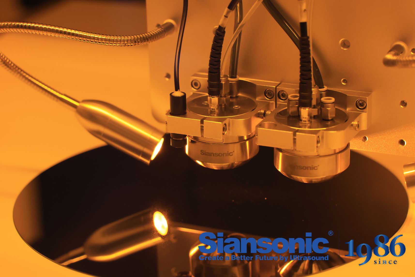
Atomization quality starts at the lip where liquid leaves the part. If that surface carries even a few microns of tool marks, the film thickness around the orifice edge changes enough to create uneven ligament breakup. Precision lapping, using a cast iron plate charged with diamond or alumina slurry, removes those marks by wearing the high spots down to a controlled flatness. The work is slow—often two to four minutes per side per grit stage—and that time cost is exactly why most production lines substitute a quick vibratory deburr or leave the machined finish as-is.
What gets missed shows up later as spray angle drift, droplet size scatter, or erosion that begins at the crest of surface roughness. Skilled lapping shops read the contact pattern on the plate and alternate the part orientation to avoid hollowing the center. They check progress with an optical flat under monochromatic light, counting interference fringes rather than trusting a profilometer spot check. Final flatness in the sub-micron range may not appear on a standard drawing, but it changes how uniformly the atomizing edge wets and releases fluid. That is why some nozzle rebuilders lap the sealing face even when the OEM assembly line never did.
Microscope Checks for Orifice Roundness—Not Just a Visual Once-Over
When a machined orifice fails a roundness spec, the root cause often hides in plain sight—but only under magnification. A naked-eye glance at a small bore might show a clean edge, yet a microscope reveals the true story: out-of-round lobes, chatter marks from tool deflection, or uneven material removal that a loupe would miss. This isn't about catching obvious defects; it's about quantifying the subtle deviations that compromise flow consistency or sealing integrity. By placing the part under a calibrated microscope with a reticle or digital overlay, you can measure diameter variance across multiple axes in seconds, turning a subjective "looks okay" into hard numerical pass/fail data.
The real value comes from the microscope's ability to freeze the inspection process. Instead of rotating a part under a fixed light and squinting for irregularities, the operator positions the orifice perpendicular to the optical axis, adjusts the illuminator to reveal edge contrast, and captures a high-resolution image. Software then traces the circumference and flags any point where the radius deviates beyond tolerance. This approach catches elliptical tendencies, burrs, or tapered entry/exit profiles that visual inspection routinely overlooks—especially in small diameters where human eyes lack the angular resolution to perceive a few microns of asymmetry.
But don't mistake this for a simple magnification exercise. Effective microscope-based roundness checking demands attention to lighting geometry, focus depth, and stage alignment. A ring light placed too close can wash out the edge, while a coaxial illuminator might create false shadows that mimic lobing. To get repeatable results, you need a stable fixture that holds the part square to the lens and a measurement protocol that averages multiple orientations. Once that discipline is in place, the microscope becomes more than a visual tool—it becomes an objective referee, catching roundness drift before the parts ship, without relying on the operator's mood or eyesight on a given shift.
Matching Resonant Frequency to Coating Rheology Instead of the Spec Sheet
Resonant frequency tuning in coating processes often begins with the spec sheet, but that document rarely captures how a fluid behaves under actual shear and oscillation. Rheology shifts with temperature, solvent flash-off, and batch-to-batch variation, so a frequency that works on paper can fall apart on the line. Instead of chasing numbers, it's more practical to watch how the coating responds dynamically across a small frequency sweep and match the resonance to the point where viscosity and elasticity stop fighting each other.
The real target is the coating's relaxation time—the point where it transitions from elastic to viscous behavior. If you tune too far above that, you get atomization issues and overspray; too far below, and the film leveling suffers because the coating can't flow before the solvent leaves. A simple way to find this is to run a quick oscillatory test on a small sample and look for the crossover of storage and loss modulus, then set the resonant frequency as a multiple of that crossover. This ties the process directly to how the material moves rather than a static viscosity value printed months ago.
Operators sometimes resist this approach because it adds a few minutes of testing, but the payoff shows up in fewer rejects from orange peel, mottling, or edge pull-back. When the resonant frequency aligns with the coating's actual rheology, the transfer efficiency typically climbs and the film thickness becomes more uniform across complex geometries. It's less about having a perfect spec sheet and more about learning to listen to what the fluid is telling you in real time.
Cleanroom Assembly That Keeps Nozzle Internals Particle-Free
All nozzle assembly work takes place inside an ISO Class 5 cleanroom where HEPA-filtered air is supplied at a rate of 300 air changes per hour. Technicians enter through an air shower and wear full coveralls, hoods, booties, and nitrile gloves. Every tool, fixture, and contact surface is wiped with 70% isopropyl alcohol before the first part is touched.
Before mating the nozzle body and tip, each internal passage is flushed with filtered deionized water and blown dry with clean nitrogen. Soft, lint-free swabs remove any residual film from machined surfaces. The components are then assembled under a laminar flow hood, and all openings are capped with cleanroom-grade plugs within seconds of final torque.
Particle counters positioned at the workstation record airborne counts every five minutes, and any excursion above the Class 5 limit pauses the line immediately. Finished nozzles are sampled and flushed with ultra-pure water, which is passed through a liquid particle counter. The acceptance criterion is fewer than ten particles larger than 0.5 microns per milliliter, a level achieved routinely without final rinsing or additional cleaning.
Final Spray Pattern Validation on the Exact Coating You Run
Lab water patterns lie. The moment you switch to the actual coating—same viscosity, solids load, and solvent package—the fan width and droplet distribution can shift enough to wreck edge coverage or pile film in the center. Running the validation on the exact material you spray, not a stand-in, is the only way to see the true breakup and deposition behavior under production conditions.
Set the gun to your line pressure and fluid tip, then spray a clean test panel or a scrap part with the same coating and the same ambient temperature. Check the wet pattern across the full width: look for a heavy center, dry shoulders, or uneven tails. If the cross-section isn't flat within your mil tolerance, adjust air pressure, fluid flow, or tip size before a single production part goes through. Record that final setup, including lot number and booth conditions, because the next batch of coating can change things just enough to matter.
FAQ
Even a few microns of deviation inside the atomizing surface can shift the standing wave nodes, which directly leads to uneven droplet distribution. A shop that relies on CNC grinding followed by laser interferometry can hold those surfaces within a fraction of a wavelength, and that consistency shows up as cleaner edge definition and fewer pinholes in the coating.
If the piezoelectric discs are bonded with too much adhesive or with voids in the joint, the transducer loses its resonant sharpness. That means the nozzle starts to modulate its frequency instead of holding a steady ultrasonic field, and the droplets become bimodal—some too large, some too fine. High-end factories use vacuum-assisted bonding and then run impedance sweeps on every unit to reject any that show secondary resonances.
A rough tip surface can trap coating residue and create nucleation points for premature droplet breakup. Polishing the tip to a mirror finish, often below 0.2 micron Ra, helps the liquid sheet detach cleanly and reduces the chance of clogging or spitting. That directly cuts down on the random streaks and fisheyes that plague many spray coating lines.
Some use inline laser diffraction systems that sample the spray plume every few seconds and feed the data back to the generator. If the Sauter mean diameter drifts outside a set band, the line automatically adjusts the power or flow rate. This closed-loop approach is much faster than pulling nozzles off the line for offline testing, and it catches drift before a full batch is coated.
A common one is misalignment between the liquid feed tube and the atomizing surface. Even a small angular error can bias the spray toward one side, creating a crescent-shaped pattern. Another is inconsistent torque on the nozzle retaining nut, which changes the preload on the piezoelectric stack and shifts the resonant frequency. Factories that use calibrated torque drivers and laser alignment checks avoid most of these issues.
Within a limited range, calibration can handle viscosity changes by adjusting the excitation voltage and flow rate. But if a coating is significantly thicker, the nozzle needs a larger orifice and a different horn geometry to maintain atomization. A good factory will characterize each nozzle design across a viscosity curve and provide a recommended operating window rather than trying to force one nozzle to do everything.
You might see coatings with a heavy buildup at the pattern edges, intermittent spitting that leaves droplets on the surface, or a spray width that changes from one unit to the next. On the nozzle itself, the tip may show tool marks or uneven plating. These defects usually trace back to loose machining tolerances, poor surface finishing, or lack of post-assembly resonance testing.
They often use accelerated life tests that cycle the nozzle through high and low power, dry and wet conditions, and rapid temperature swings. After each cycle, they re-check the impedance, flow rate, and droplet spectrum. A nozzle that holds its resonant frequency and droplet size within a narrow band after thousands of cycles is very likely to maintain coating quality in the field.
Conclusion
The most meaningful gains in ultrasonic spray nozzle coating quality often trace back to factory processes that never appear on a datasheet. For instance, droplet size is locked in before the nozzle ever leaves the bench, with technicians verifying atomization performance under controlled fluid conditions rather than relying on generic calculations. The atomizing surface is then precision lapped to a flatness and finish that many production lines skip, which directly stabilizes the standing wave that breaks the liquid into uniform droplets. Under a microscope, each orifice is checked for true roundness and edge integrity, because even a slight deformation can split the spray pattern or create satellite droplets. Resonant frequency is not simply matched to a spec sheet; it is tuned against the actual coating rheology, accounting for viscosity, solids loading, and surface tension so the nozzle operates at its natural harmonic peak with the real fluid.
Assembly takes place in a cleanroom environment to keep internal passages free of particles that could clog the orifice or disturb the acoustic field. Finally, every nozzle is validated by spraying the exact coating formulation the customer runs, not a substitute liquid, and the resulting pattern is measured for width, uniformity, and edge definition. This end-to-end approach means the nozzle arrives ready for production, not ready for further adjustment. Together, these factory-level disciplines eliminate the hidden variables that typically degrade coating consistency, adhesion, and repeatability in high-precision applications.
Contact Us
Contact Person: Ivy Zhang
Email: [email protected]
Tel/WhatsApp: +86 1081502288
Website: https://www.siansonic.com/